Towards Automatic Traceability in Industrial Practice
Ian Alexander
Independent Consultant
Proceedings of the First International Workshop on Traceability,
Abstract Traceability is agreed to be essential but it is avoided on many industrial projects both through unfamiliarity and because it is burdensome. Semi-automatic traceability tools promise the beginnings of a solution to these twin problems. This paper describes experience with a toolkit that helped to reduce the burden of installing traces and allowed readers to view traces with familiar tools. Three traceability tools were used: an analyser that can automatically link Use Case references to Use Cases; a dictionary builder that links and if need be creates definitions from marked-up terms; and an exporter that translates a database of Use Cases into a fully-navigable and fully-indexed hypertext. The advantages and limitations of this toolkit are discussed in the context of a railway control system project.
Edinburgh, 28th September 2002, pp 26-31,
in conjunction with the 17th IEEE International Conference on
Automated Software Engineering
Introduction and Approach
Traceability is essential for many purposes, including assuring that systems conform to their requirements, that terms are defined and used consistently, and that the structures of models correspond to requirements. Unfortunately the effort needed to install complete sets of traces is quite large, as traceability is usually many-to-many so there are typically more traces than requirements. Clearly, tool support can sometimes reduce the burden. Where there is enough information in an item (such as a requirement or use case step) to resolve a reference precisely, a custom tool can automatically translate the reference into a trace. For example, a glossary tool can scan a text for marked-up terms and populate a dictionary with them, making definition traces at the same time. Requirements database tools such as [DOORS 2002] can therefore be used as environments for semi-automatic installation of traces; such tools already provide effective support for recording, displaying, and checking the completeness of installed traces.
However, requirements tools remain unfamiliar to many engineers, and even where such tools are in service in a company, there are often practical limits on their use, such as shortages of tool skills and limited access to database client workstations. The problem of unfamiliarity can be reduced by translating data structures into a familiar form such as a hypertext. Engineers can then explore traceability networks with nothing more special than a web browser. As it happens, DOORS provides a simple exporter that maps each module (representing e.g. a document) to a single web page. It is straightforward to use the DOORS programming language DXL to create a custom exporter. This tool can in its turn translate specialised data structures such as Use Case models into fully-navigable hypertexts with, for example, a web page for each Use Case, linked to its actors and to the cases that include or are included by it.
None of these techniques are dramatic innovations, but together they are starting to help engineers in industry make better use of traceability in higher-quality specifications.
Related Work
[Kotonya and Sommerville 1997] write that despite the importance of traceability there is surprisingly little written about it (p 136), but they mention [Palmer 1996]’s sensible and thorough introduction, which sketches the basic life-cycle to show why traceability matters. So do [Stevens et al 1998] in their practical tour of Systems Engineering (pp 269-272).
Tool vendors are keen to provide effective support for such processes [e.g. DOORS 2002, Requisite Pro 2002] and indeed there is scope for simple industrial advice on the use of traceability tools [Alexander & Stevens 2002, pp 92-95]. [Ebner & Kaindl 2002] describe semi-automatic installation of traces with the RETH tool, while [Kaindl et al 1999] also describe a glossary-linking tool.
Use Cases [Jacobson et al 1992] have by now a set textual form [e.g. Cockburn 2000] which has been implemented on the DOORS platform [ScenarioPlus 2002] and applied in e.g. a trade-off workshop [Alexander 2002]. These disparate strands offer the possibility of a unified approach to installing and benefiting from traceability on a suitable platform.
Traceability is of course a built-in feature of DOORS and similar requirements tools. However DOORS does not provide a way of structuring traces into groups such as by Goals or Use Cases – traces are seen as belonging purely to atomic objects (such as individual requirements or test steps). Manual creation of structure would have been time-consuming (and hard to maintain), and export to a single Web page using the standard exporter would have been unreadable and hard to search (with no index or graphical navigation).
Use of a drawing package such as [Visio 2002] for Use Case diagrams would have handled the (not especially complex) diagram-drawing aspects easily, but would have removed the advantages of DOORS traceability to other items such as definitions, requirements, and tests.
Use of a Computer-Aided Software Engineering (CASE) tool such as [Tau 2002] to construct Use Case objects with supporting snippets of text would have enabled efficient navigation between objects but would have introduced yet another new tool – more specialized than DOORS; it would also have required traces to requirements held in DOORS or elsewhere, and to an external dictionary.
Tools Used
The underlying platform for this project was DOORS which provides document-like modules containing objects that can be linked individually, and crucially a programming language DXL with full access to the tool’s data structures. The Scenario Plus toolkit is a family of DXL scripts that support Use Case and other models.
Use Case Modelling
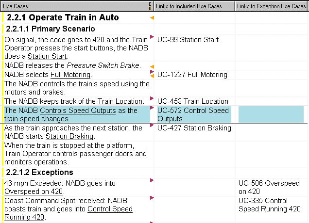
Three devices are used to ensure correct linking (Figure 1):

Figure 1: Semi-automatic Installation of Traceability in a Railway Use Case Model
(The use case text on the left has been marked up manually;
the analyser has identified and created links to the use cases as shown on the right)
Project Dictionary Construction
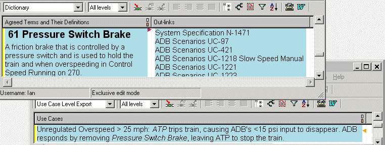
The dictionary tool similarly searches the text (in any selected module) for marked-up phrases. It matches these (allowing for plural forms) with terms in the project dictionary module and links them with ‘defines terms in’ traces. If no match is found a new dictionary object is created with the term as its heading, linked, and left for an engineer to supply a definition in the object text (Figure 2). Finally, if there is no dictionary module, all the needed data structures are created and populated.

Figure 2: Semi-automatic installation of a Project Dictionary.
(The use case text at the bottom has been marked up manually;
the dictionary entry at the top has been created and linked in many places as shown,
and the dictionary definition has then been supplied manually.)
Navigable Use Case Export
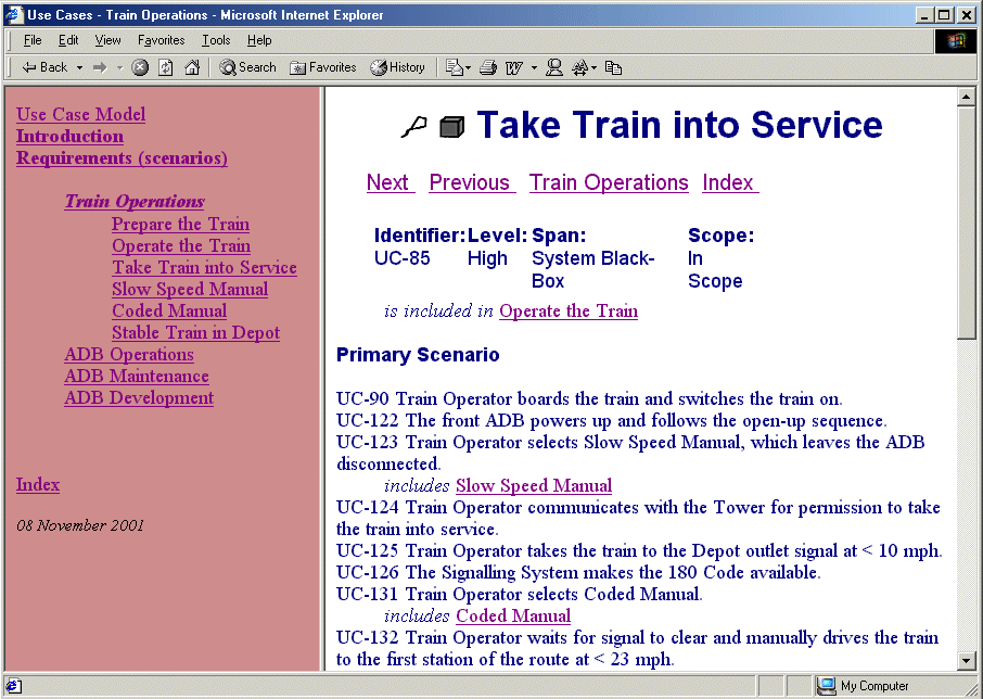
The third tool, a specialised Use Case model exporter, traverses a module and writes a set of web pages consisting of a frameset with an index frame on the left and a main frame on the right (Figure 3). The Introduction contains an auto-generated summary and a list of the Actors, linked to the Use Cases in which they act: the Actors page can be seen as an actor-centred index to the use case model. The left-hand frame works like "Sherlock Holmes’ Lens", giving detail of the immediate context such as the use cases in the current diagram (‘Train Operations’ in Figure 3) but only an overview of other parts of the model.
Traces between use cases are naturally presented as hyperlinks. Since HTML links are typeless, the type of the DOORS relationship is stated (in italics); at the same time, the direction of the link is indicated by phrasing the relationship actively if it is forwards, e.g. ‘includes …’, and passively if it is a reverse link e.g. ‘is included in Operate the Train’; DOORS links can be followed in either direction, so two hyperlinks are required for each DOORS link.
An alphabetical index and a graphical index in the form of an image-mapped use case diagram (a click on a use case bubble navigates to that use case), along with conventional next/previous and parent navigation also help to make the model and its traceability structure as easy to explore as possible.
Navigating to another diagram with a standard Web browser causes the index page for that diagram to be loaded (i.e. there is a hyperlink to a different HTML frameset, with its own index frame on the left and the use case diagram on the right) to give the effect of the "Lens" moving over the hypertext. The equivalent links can be followed while editing within the DOORS environment using the standard point-and-click link navigation, and also graphically through a display of the use case diagrams created in DXL.

Figure 3: Traceability translated into familiar Hypertext on a Railway Project
Experience on a Railway Control System Project
A project to replace a train control box on a commuter railway had to prepare a set of specifications in a short timescale as the old components could no longer be obtained, and the system was needed to operate the railway. The new system had essentially two goals: to provide the same control as the old one, and to provide better braking by measuring deceleration and applying finer control of the motors, using them as rheostatic brakes by forcing them to drive electric power back into the supply grid.
Workshops and interviews with operations, control, and braking specialists were used to elicit scenarios (and non-functional requirements). A Use Case model was constructed iteratively, and corrected in follow-up sessions with the specialists who quickly adapted to the scenario approach. As the model evolved, it had to be reshaped. This was greatly facilitated by the automatic analyser, as it permitted the project to create or rename Use Cases to reflect new understanding, to edit the normal and exception scenarios (removing any incorrect steps), and simply to underscore any new references to other Use Cases. The analyser then rebuilt the correct types of links to the correct targets and updated the Use Case diagrams automatically.
It became clear that the requirements had previously been thought of from the point of view of the control box, with little attention either to the operational context (what the train was doing on the track, in the depot, etc), or to other situations such as maintenance and indeed development testing. For example, maintenance demands help with diagnosis; development testing similarly implies a need for automatic test equipment able to simulate the train and the track, given that verification is essential in any control system, and that time on track in a test train is costly, a scarce resource, and only really applicable when a control box is available in close-to-final form (with all interfaces connected).
Thinking through operations, starting with simple questions like ‘describe a typical day in the life of the control box’, quickly helped to elicit scenarios such as taking the train into service (Figure 3), and hence to exceptions such as conditions that could prevent the train from going into service. In turn, this led to the realization of the implications of a failure operationally. Safety is not threatened as the train’s safety unit automatically stops the train if the control box fails; but even though the control box ‘can be replaced in 5 minutes’, a stopped train many miles from the depot may block the line and other trains for much longer than that.
The specification grew to cover a simulator, other test equipment and non-functional requirements such as the weight, size, accessibility and reliability of the control box, all tracing back to the scenarios.
Some concepts proved to be contentious, as a range of broader and narrower, older and newer terms were in use. Terms were documented in the project dictionary as they were discoverered, and reviewed by the specialists. For example, as mentioned the control box is safety-related but not at a high Safety Integrity Level (SIL) because it is protected by a safety unit providing Automatic Train Protection (ATP). Any safety-related system has to gain approval by the safety authorities. One way to help achieve this is to show that a new system is equivalent to an old one. However ‘equivalence’ is a difficult term, as it can mean physical (wiring layout) isomorphism: clearly unattainable if any new functions were to be added, and indeed if modern micro-electronics were to be used (as was inevitable). The simple act of defining ‘physical equivalence’ and ‘functional equivalence’ in the project dictionary and linking the latter to the safety requirements quickly took the heat out of the discussions.
The Use Case model was periodically exported for informal review by the specialists, who either browsed it as a hypertext or received a copy printed from the hypertext. This elicited many comments which were fed back into the model as corrections; the model was then updated and relinked as already described.
Meanwhile the functional requirements were prepared from a combination of the old specifications with inputs from the scenarios, making tracing a largely manual process which was further delayed by the late installation of DOORS at a key site.
The non-functional requirements were elicited by preparing a hierarchical classification of the categories considered likely to be needed. This was then populated with reference to railway standards, demanding inputs from several specialists in different disciplines, whose time was invariably scarce. This process too was labour-intensive, involving cutting and pasting from many sources.
Benefits, Limitations, and Opportunities for Further Work
The tooling enabled the Use Case model to be elicited, built, fully linked, and then reviewed and reworked to a good state within a month. The Dictionary was constructed and fully traced, again to good quality, at the same time.
The need for manual tracing between Use Cases and requirements, along with staff training, schedule and programmatic limitations meant that these traces progressed much more slowly. Presumably the same would have happened to the Use Cases and to the Dictionary traces without the special tooling.
Paper remained an important communication medium, as did ordinary word-processing and email. The use of hypertext helped to reduce the ‘energy barrier’ to the use of more specialised requirements and traceability tooling but did not eliminate it.
The process of installing traces between requirements and Use Cases could have been partly automated through simple one-to-one copying-and-linking (a facility built into DOORS), if only the requirements could have waited until the scenarios were complete. This was not possible, both because cut-and-paste reuse was already well advanced, and because requirement revision continued concurrently with scenario elicitation. Progress towards automating this step – or even eliminating it if the industry were to accept functional requirements in the form of Use Cases – would be desirable. However there remain large obstacles to the latter course, including standardization, expectations held by both customer and suppliers, training needs, and political fragmentation.
It would be attractive to automate railway Standards by restructuring them in a database and providing a semi-automatic reuse mechanism to copy and link (and even to give advice on the selection of) relevant clauses into product specifications. The process is today largely manual, made more complex by the many layers of overlapping and contradictory regulation, e.g. European and UK laws; industry standards and best practice; specific prescriptive standards for different asset types. London Underground is now working towards such a database with a major redrafting of all its standards, which will affect all the railways in London and may well have much wider influence.
Conclusions
The tools worked well, making a rapid iterative development of scenarios and a project dictionary possible. The principle of using a requirements tool to provide support for traceability and modelling, if not fully established, is at least seen to be desirable.
Several major traceability challenges remain, but the approach has already contributed to creating a better-documented and more complete set of specifications for a train control box.
References
Alexander 2002: Ian Alexander, Initial Industrial Experience of Misuse Cases in Trade-Off Analysis, Proceedings of the IEEE Joint International Requirements Engineering Conference (RE'02), 9-13 September 2002, Essen, Germany
Alexander & Stevens 2002: Ian Alexander and Richard Stevens, Writing Better Requirements, Addison-Wesley 2002
Cockburn 2001: Alistair Cockburn, Writing Effective Use Cases, Addison-Wesley, 2001
DOORS 2002: website of Telelogic, http://www.telelogic.com
Ebner & Kaindl 2002: Gerald Ebner and Hermann Kaindl, Tracing All Around in Reengineering, IEEE Software, May/June 2002, pp 70-77
Jacobson 1992: Ivar Jacobson, M. Christerson, P. Jonsson, and O. Gunnar: Object-Oriented Software Engineering: A Use Case Driven Approach, Addison-Wesley 1992
Kaindl et al 1999: Hermann Kaindl, S. Kramer, and P.S.N. Diallo, Semiautomatic Generation of Glossary Links: A Practical Solution, Proc. 10th ACM Conference on Hypertext and Hypermedia (Hypertext 99), ACM Press, New York, 1999, pp 3-12
Kotonya & Sommerville 1997: Gerald Kotonya and Ian Sommerville, Requirements Engineering, processes and techniques, Wiley 1997
Palmer 1996: James D. Palmer, Traceability, in [Thayer & Dorfman 2000] pp 412-422
Requisite Pro 2002: website of Rational, http://www.rational.com
Scenario Plus 2002: website (free Use Case toolkit for DOORS), http://www.scenarioplus. org.uk
Stevens et al 1998: Richard Stevens, Peter Brook, Ken Jackson and Stuart Arnold, Systems Engineering, coping with complexity, Prentice Hall 1998
Tau 2002: website of Telelogic, http://www.telelogic.com
Thayer & Dorfman 2000: Richard H. Thayer and Merlin Dorfman, Software Requirements Engineering, 2nd Edition, IEEE Computer Society, 2000
Visio 2002: website of Microsoft, http://www.microsoft.com